Carbon Fiber Prototyping Services
Carbon fiber prototyping services let engineering and sourcing teams prove a design’s form, fit, and structural behavior before committing to expensive production tooling. Because carbon fiber is a directional, layered material, a prototype that is merely “the right shape” can still fail in service if the layup, radii, and draft were wrong. Since 2005 TechCarbonWorks has helped customers in the United States, Europe, and Australia move from CAD to a credible composite prototype in as little as one to three weeks, using rapid tooling routes that keep cost low while preserving the lessons needed for production.
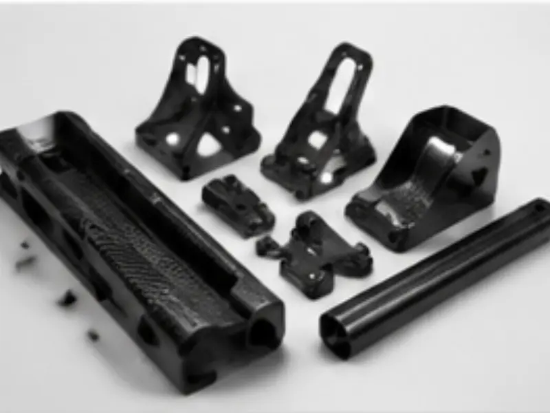
Prototype carbon fiber components built through rapid tooling and composite layup for design validation.
Why Prototype in Carbon Fiber
A metal or 3D-printed mock-up will not tell you how a carbon part behaves. Carbon fiber is anisotropic: stiffness and strength run with the fiber, and a part can be rigid in one axis yet flexible in another. Prototyping in the actual composite reveals layup-driven warpage, resin-rich zones, and bonding challenges that only appear once the material is cured. Our carbon fiber prototyping services therefore aim to deliver a part made by a route that mirrors production, so the data you collect transfers directly to the manufacturing phase.
Rapid Tooling Routes
The speed and cost of a prototype are mostly set by the tooling choice. We offer three primary rapid tooling routes.
- Machined tooling board: A high-density syntactic board is CNC-cut to the negative shape. It is cheap, fast (often one day of machining), and ideal for a single wet-layup or vacuum-bag part. Tooling board suffers at high cure temperatures, so it suits room-temperature and moderate-heat prototypes.
- 3D-printed molds: Resin or filament printed molds handle complex curvature and organic shapes that would be slow to machine. They are best for low-temperature cure and very low volumes, and they let us test geometry in days.
- Composite molds: A fiberglass or carbon toolface backed with a stiff core, often made from a machined master. Composite molds survive prepreg and autoclave cycles and deliver class-A surface, making them the natural bridge to production.
| Tooling Route | Lead Time | Temp Limit | Surface | Best Use |
|---|---|---|---|---|
| Machined tooling board | 1-2 days | Low to moderate | Good | Single quick mock-up |
| 3D-printed mold | 2-4 days | Low | Fair | Complex organic shape |
| Composite mold | 1-2 weeks | High (prepreg) | Class-A | Bridge to production |
| Aluminum mold | 2-3 weeks | Very high | Excellent | Production bridge |
Wet Layup vs Prepreg Prototypes
The two dominant laminating methods each suit different prototype goals. Wet layup uses dry fabric impregnated by hand with resin, then vacuum-bagged and cured at room or mildly elevated temperature. It is the fastest and least expensive way to get a carbon part, but resin content varies and voids are harder to control. It is perfect for fit checks and non-critical structural mock-ups.
Prepreg uses fabric pre-impregnated with a precise resin amount, stored cold and cured under heat with vacuum or autoclave pressure. The fiber fraction is controlled, voids are low, and mechanical properties approach production aerospace standards. Prepreg prototypes cost more and take longer but give trustworthy structural data. Many carbon fiber prototyping services programs start wet and move to prepreg once the geometry is settled.
Design-for-Composites Feedback (DFM)
The single biggest source of wasted prototype budget is a CAD model drawn like a metal part. Carbon fiber hates sharp internal corners, uniform thin sections, and flat bond faces without draft. Our DFM review, included with every prototype, flags these issues and proposes fixes: generous radii to avoid stress concentration and layup bridging, taper so the part releases from the mold, balanced wall thickness to prevent warpage, and bonded inserts placed where the laminate can carry the load.
We return marked-up drawings and a short engineering note so your team understands not just what to change but why. This feedback loop is where most programs save their real money, because a corrected design prototypes once instead of three times.
Iteration Cycles
Iteration is expected, not penalized. With machined tooling board or 3D-printed molds we can often deliver a revised part in three to five days per cycle, letting teams refine geometry, thickness, and insert placement across several loops. We track each cycle’s layup book, cure parameters, and measured dimensions so the final configuration is fully documented and ready to promote.
Because tooling board molds are inexpensive, engineers feel free to break things on purpose, testing worst-case loads and assembly fits before any production commitment. That freedom is the point of prototyping.
Documenting Each Loop
Every iteration is recorded in a running prototype log: the CAD revision, the mold route, the layup schedule, the cure parameters, and the measured outcome. By the final cycle you hold a complete record that reads directly into production documentation, so the knowledge earned in prototyping is not lost when the program hands to manufacturing. Teams that skip this discipline often re-learn lessons later at far higher cost, which is why disciplined record-keeping is built into our carbon fiber prototyping services rather than left to chance.
Prototype-to-Production Bridge
A good prototype program should not end in a drawer. We design the carbon fiber prototyping services engagement so the tooling and process qualify for production. A composite mold proven during prototyping becomes the production tool; the layup schedule and cure cycle are written as controlled documents; first-article data seeds the inspection plan. When volumes rise, we promote the same mold family to aluminum or add cavities rather than reinventing the process.
This bridge protects your schedule. Tooling re-qualification is one of the longest delays in composite programs, and our approach removes it.
Cost Visibility Across the Bridge
A benefit teams underestimate is cost clarity. Because the prototype tool and process are the production tool and process, the per-part cost you see at prototype volume scales predictably to production, with the main change being material buying power and cycle time. You avoid the unpleasant surprise of a cheap prototype followed by an unaffordable production quote from a different method. Our carbon fiber prototyping services therefore double as a quiet cost-engineering exercise, revealing where a small design change trims cycle time or scrap before volume commits.
Materials and Processes
Prototypes can be built from woven twill, unidirectional, or hybrid glass-carbon fabrics, using epoxy, vinyl ester, or toughened aerospace resin systems depending on the target properties. We support hand layup, vacuum infusion, prepreg, and autoclave cure, and we can embed metal inserts, foam cores, and honeycomb to mimic the production sandwich construction your part will eventually use.
Core Materials and Sandwich Builds
Many production carbon parts are not solid laminate but a sandwich: thin composite skins over a lightweight core such as PVC foam, PET foam, or aluminum honeycomb. Prototyping the sandwich matters because core density and skin thickness drive stiffness and crush resistance. We build prototype sandwiches with the same core your production part will use, so a flex or impact test on the prototype predicts the real component. Skipping the core in a prototype is a common mistake that hides a stiffness problem until production, and our carbon fiber prototyping services deliberately avoid it.
Inserts, Bonding, and Assembly Checks
Structural prototypes usually need metal inserts, bushings, or bonded brackets. We mold or bond these during the prototype build and then test the assembly fit against your mating hardware. A prototype that proves the laminate but fails at the insert pull-out teaches you nothing useful, so we validate the bond line, the insert torque-out, and the clearance to adjacent parts while the tooling is still cheap to change.
Mechanical Validation Support
Beyond shape, teams often need to know a prototype will carry load. We can supply companion coupon samples from the same layup for tensile, flexural, or shear testing, and we document the cure cycle so test data links to the part. For programs moving toward certification, this coupon-to-part traceability started in prototyping smooths the later qualification effort.
Functional vs Cosmetic Prototypes
Before choosing a route, a program must decide what the prototype is actually for, because a cosmetic mock-up and a functional test article are built very differently. Our carbon fiber prototyping services separate these two goals explicitly so you do not overpay for a show model or underbuild a structural proof.
A cosmetic prototype exists to validate appearance, ergonomics, and assembly fit against surrounding parts. It needs the right surface, the right contour, and the right clearances, but it does not need production-grade fiber fraction or certified laminate data. For these we lean on machined tooling board with wet layup or a 3D-printed mold, delivering convincing visual and fit samples quickly and cheaply.
A functional prototype must behave like the production part under load, heat, or fatigue. Here we use prepreg or infusion with a controlled layup book, build the correct sandwich core, and embed the real inserts so the test article carries representative strain. The data from a functional prototype feeds FEA correlation and certification evidence, so material and process fidelity are non-negotiable. Many programs begin with a cosmetic part to lock shape, then promote to a functional build once the geometry is agreed, which is the most efficient way to spend prototype budget.
Matching the Prototype to the Decision
We help teams map each prototype to the specific decision it supports. A design review needs only a cosmetic article; a load qualification needs a functional one; a supplier audition needs both. By stating the decision up front, we avoid the classic error of building an expensive prepreg part to answer a question a tooling-board mock-up could have settled, or conversely building a weak wet-layup part and trusting it for a structural claim.
Prototype Tooling Cost and Lead-Time Comparison
Cost and lead time scale directly with the tooling route, and the table below gives the relative picture most teams need when budgeting a program. Absolute numbers depend on part size and complexity, but the ordering is consistent across programs.
| Tooling Route | Relative Tool Cost | Unit Part Cost | Lead Time to First Part | Rework Speed | Best For |
|---|---|---|---|---|---|
| Machined tooling board | $ | $$ | 1-2 days | 3-5 days per cycle | Single fit mock-up |
| 3D-printed mold | $$ | $$ | 2-4 days | 3-5 days per cycle | Organic complex shape |
| Composite mold | $$$ | $ | 1-2 weeks | New mold per major change | Bridge to production |
| Aluminum mold | $$$$ | $ | 2-3 weeks | New mold per major change | Production bridge runs |
The key insight is that cheap tooling buys cheap iteration. Tooling board and 3D-printed molds are so inexpensive that teams can afford to deliberately break parts while learning, whereas a committed aluminum tool discourages late changes. Our carbon fiber prototyping services deliberately keep early cycles on disposable tooling, then move to durable tooling only after the design is stable, which is where the total program cost is actually minimized.
Budgeting the Iteration Loop
When we quote a prototype program we quote the first part and the expected revision cycles together, not as surprise add-ons. A typical cosmetic-to-functional program runs three to six cycles, and budgeting them up front lets purchasing compare our route against an in-house 3D print honestly. The comparison usually favors composites the moment a real surface or structural claim enters the picture, because printed plastic cannot mimic carbon’s stiffness or finish.
Materials for Prototypes: T300 vs T700, Twill vs Plain
Material choice shapes both the look and the data. For prototyping we most often select between two workhorse fibers and two weave styles.
T300 vs T700: T300 is a standard-modulus fiber with decades of aerospace pedigree, good toughness, and forgiving handling, making it the default for most prototypes where the goal is fit and general strength. T700 offers roughly 15 to 20 percent higher tensile strength and better strain to failure, which matters when the prototype must demonstrate margin or survive impact-style loading. We recommend T300 for early cosmetic and fit work and step up to T700 when the functional prototype must carry real load or feed a certification case.
Twill vs plain weave: Twill weave, with its diagonal 2x2 pattern, drapes smoothly over compound curves and looks striking, which is why it dominates cosmetic prototypes and visually exposed parts. Plain weave is tighter and more stable, with less bias elongation, giving better dimensional predictability on flat or lightly curved structural plates. For a cosmetic show part we default to twill; for a functional laminate plate we often prefer plain. Both are available in our carbon fiber prototyping services, and the choice is recorded in the layup book so production matches the validated build.
Resin System Selection for Prototypes
Beyond fiber, the resin sets the cure path and the data quality. Room-temperature epoxy suits fast wet-layup mock-ups; aerospace-grade toughened epoxy prepreg suits functional articles that must approach production properties. We also run vinyl ester where chemical resistance is part of the prototype’s test, and we match the resin to the production intent so the prototype does not mislead the team about real-world behavior.
Testing and Validation Support
A prototype earns its keep only when it is tested, and our carbon fiber prototyping services include structured validation support so the part is not just built but proven.
Fit checks: We mount the prototype against your mating hardware, fixtures, or adjacent components and record clearance, fastener engagement, and interference. Where the mating part is supplied, we confirm the assembly; where it is not, we build a simple check fixture so the dimension is verified objectively rather than by eye.
Load tests: For functional articles we perform or support proof loading, three-point flexural checks, and insert pull-out or torque-out tests, either in our shop or alongside your test lab. We instrument the part with strain mapping where needed so the failure mode is understood, not just observed.
Coupon correlation: Because we laminate companion coupons from the identical layup and cure, your lab data ties directly to the part. This coupon-to-part traceability, started in prototyping, smooths later certification and removes the common gap between “the material data sheet says” and “this actual part does.”
Documenting Validation Outcomes
Every test we run is written into the prototype log with the setup, the load, the result, and the pass or fail against your stated requirement. That record becomes the evidence base when the program moves to production qualification, so the validation work done at prototype volume is not repeated or questioned later.
Iteration Case Walkthrough
To make the process concrete, consider a representative UAV boom arm program. The customer arrived with a CAD model drawn like an aluminum tube and asked for a stiff-light replacement.
Cycle 1: We machined a tooling-board mold and wet-layup a twill T300 boom in five days. Fit check against the airframe revealed a 1.2 mm interference at the root and a sharp internal corner that bridged during layup. DFM feedback proposed a 2 mm radius and a 1.5 mm clearance.
Cycle 2: Revised mold and prepreg T700 plain-weave boom with a PET foam core. Three-point flexural test showed 18 percent below target stiffness because the core was too soft. We increased skin thickness and moved to a higher-density core.
Cycle 3: Final configuration passed flexural and insert torque-out. The composite mold was promoted to the production tool, the layup book was frozen, and first-article data seeded inspection. Total elapsed was under four weeks, and the customer avoided committing an aluminum tool to a design that changed twice.
This walkthrough is typical of how our carbon fiber prototyping services turn an uncertain CAD file into a qualified production-ready configuration without a single wasted metal tool.
Bridge-to-Production Planning
The bridge from prototype to production is a plan, not an afterthought. We define it during the first quotation so the tooling and process chosen at prototype volume are the ones that scale.
Tooling Promotion Path
We specify at the start which prototype mold becomes the production tool and at what volume we add cavities or promote to aluminum. A composite mold proven on the prototype runs bridge production; when annual volume crosses a threshold we machine an aluminum multi-cavity tool using the same qualified geometry, so there is no re-qualification gap.
Process Documentation Hand-Off
The layup book, cure cycle, release procedure, and inspection plan written during prototyping are handed to production as controlled documents. Your production team receives a ready process rather than a vague “we made it work” memory, which is the single biggest reducer of launch risk.
Risk and Cost Lock
Because prototype and production share a method, the per-part cost seen at prototype volume scales predictably, and the residual risks (warpage, insert pull-out, surface) are already retired. Our carbon fiber prototyping services therefore deliver not just a part but a de-risked, costed, documented path to volume, which is the outcome most engineering teams actually need.
Industries Served
Our prototype work spans UAV frames and arms, aerospace brackets, motorsport aero devices, robotics links, and medical housings. Each brings different priorities: aerospace needs traceable prepreg data, motorsport needs fast iteration, robotics needs stiff-light geometry. We tune the prototype route to the sector’s real constraint rather than applying one method to all.
For deeper background, our carbon fiber prototyping services main page outlines program steps, and the carbon fiber manufacturing blog shares recent case studies. Start from our carbon fiber manufacturing services overview or the custom carbon fiber parts manufacturer profile. Related capabilities include CNC machining carbon fiber parts, carbon fiber mold making service, aerospace carbon fiber parts, and robotics carbon fiber parts. The UAV carbon fiber components and motorsport carbon fiber parts pages show sector examples.
Why TechCarbonWorks
Founded in 2005 in Dongguan, China, TechCarbonWorks is an ISO 9001 certified composite manufacturer shipping worldwide to the US, Europe, and Australia. Our integrated prototyping, tooling, and molding teams mean your prototype and your production tool come from one accountable source, with engineering continuity from first sketch to final shipment.
Start your prototype program today by emailing [email protected] with your CAD files, target properties, and expected volumes. We will propose the fastest, lowest-risk route and quote a firm lead time.