CNC Machining Carbon Fiber Parts
CNC machining carbon fiber parts is one of the most demanding operations in composite manufacturing because the same stiffness and hardness that make the material attractive also destroy ordinary cutting tools and cause delamination if the process is not tightly controlled. At TechCarbonWorks we have machined carbon fiber laminates, tubes, and molded blanks since 2005, building a process chain that delivers clean edges, repeatable tolerances, and verified quality for engineering teams in the United States, Europe, and Australia. This page explains how we select machines, tooling, and inspection methods so that your drawings become production-ready carbon components rather than frayed, dimensionally drifting rejects.
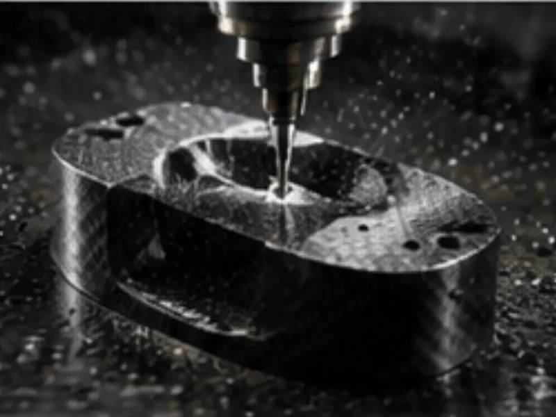
Five-axis CNC machining of carbon fiber components with diamond-coated tooling and vacuum dust extraction.
Why Carbon Fiber Needs a Specialized Machining Process
Carbon fiber reinforced polymer (CFRP) is not a uniform metal. It is a layered composite of high-strength carbon tow embedded in an epoxy or thermoplastic matrix. The fibers are harder than tool steel, the matrix is abrasive, and the laminate structure is prone to interlaminar splitting when a cutting edge pulls rather than shears. A standard end mill designed for aluminum will quickly wear, generate heat that softens the resin, and tear plies apart at the edge. That is why dedicated CNC machining carbon fiber parts programs start with tool selection and fixturing, not just a CAD-to-G-code pipeline.
Our machining group works from your STEP, IGES, or DWG files and treats every job as a composite-cutting problem first and a geometry problem second. The goal is a chip-free, sealed edge, a dimension that holds across the full production run, and a surface that needs no secondary filler before bonding or coating.
3-Axis vs 5-Axis Machining
Most flat plates, brackets, and gusset components are produced on 3-axis vertical machining centers where the spindle moves in X, Y, and Z while the part sits fixed. Three-axis work is fast, inexpensive to fixture, and ideal for drilled hole patterns, pockets, and profile cuts on sheet stock up to about 25 mm thick. For parts with compound curvature, draft angles, or features on multiple faces, a 3-axis machine forces multiple setups and introduces cumulative locating error at each re-clamp.
Five-axis machining adds two rotary axes so the cutting head or table can tilt and rotate the workpiece in a single setup. This matters for CNC machining carbon fiber parts because contoured aerodynamic surfaces, tube intersections, and molded shell trims can be reached at the optimal tool-normal angle, reducing tool deflection and producing a cleaner cut. The trade-off is programming complexity and fixture cost, which we justify on parts where accuracy and surface finish outweigh the setup premium.
| Capability | 3-Axis Machining | 5-Axis Machining |
|---|---|---|
| Best geometry | Flat plates, brackets, ribs | Contoured shells, tubes, compound angles |
| Setups required | 1 to 3 per part | Usually 1 |
| Typical tolerance | ±0.1 mm | ±0.05 mm on critical faces |
| Edge quality | Good with proper tooling | Excellent, minimal hand finishing |
| Fixture complexity | Low | Higher, rotary or vacuum |
| Cost profile | Lower | Higher, justified on complex parts |
Cutting Carbon Without Delamination
Delamination is the failure mode every engineer fears: plies separate, moisture enters, and the part loses compression strength. We prevent it through four interlocking controls. First, compression routers and up-cut/down-cut geometry that squeeze the top ply against a sacrificial backing board so fibers are sheared rather than lifted. Second, polycrystalline diamond (PCD) and diamond-coated tools that stay sharp far longer than carbide, keeping cutting forces low. Third, shallow axial depth of cut with higher spindle speeds and modest feed, a chipload strategy that avoids the heat and pull-out that tear laminates. Fourth, climb cutting and sharp, frequent tool changes so the edge never dulls into a fiber-ripping wedge.
Edge sealing follows machining for any part exposed to service environments. We apply edge sealer, UV-cure resin, or bonded edge strips to stop capillary moisture wicking into the cut laminate. This is especially important on tube cuts and drilled through-holes where the exposed ply edge would otherwise act like a wick.
Tolerances and Dimensional Control
Standard production tolerance for machined carbon fiber is ±0.1 mm, with critical datum faces and bores held to ±0.05 mm. Because CFRP has a low coefficient of thermal expansion compared with aluminum, dimensional stability after machining is excellent provided the part is allowed to relax from any machining stress. We stress-relieve large plates by roughing, releasing, and finishing in a second operation, which removes warpage before the final cut.
Tolerances tighter than ±0.05 mm are possible on local features but require hardened reference fixtures and may need in-process gauging. Our engineering team will tell you during design review where tight tolerances add cost and where a looser envelope is perfectly safe.
Tool Wear Monitoring and Process Stability
Diamond and PCD tooling holds an edge far longer than carbide, but it is not infinite. We track cut length and part count per tool and replace inserts on a scheduled basis rather than waiting for edge breakdown, because a tool that is dulling produces rising cutting forces that threaten both edge quality and datum accuracy. On long production runs we log tool life against measured edge roughness so the next batch is planned before any drift appears. This disciplined approach is what lets a bracket machined today match one machined months later, and it is the quiet difference between a shop that cuts carbon occasionally and one built around CNC machining carbon fiber parts as a core process.
Post-Machining Finishing
After the cut, parts may receive light deburring, edge sealing as described above, and where required a surface prep such as light abrasion or peel-ply exposure for secondary bonding. Holes that will carry inserts are often chamfered and cleaned of fugitive dust so the bonded insert achieves full shear transfer. We treat finishing as part of the machining operation, not a separate afterthought, so the component ships ready for assembly.
Machining Sheets, Tubes, and Molded Parts
CNC machining carbon fiber parts spans three distinct substrate families, and each needs a different fixturing approach.
- Sheets and plates: Machined from consolidated laminate stock on a vacuum or clamp table with a backing board. Profile cutting, pocketing, and hole patterns are routine.
- Tubes: Pultruded and filament-wound tubes are mounted on a rotary fourth axis and cut, chamfered, slotted, or drilled without crushing the wall. We use soft jaws and internal mandrels to prevent ovalization.
- Molded near-net blanks: Contoured shells and brackets are rough-trimmed near net, then finish-machined on 5-axis centers to final contour and hole pattern, removing the flash and draft that molding leaves behind.
Understanding which substrate you are starting from determines tool path, support strategy, and inspection plan.
Dust Extraction and Operator Safety
Carbon dust is fine, electrically conductive, and a known respiratory irritant. Machining CNC machining carbon fiber parts without proper control releases airborne fines that settle in electronics and lungs alike. We run enclosed machining cells with dedicated cyclonic pre-separation and HEPA filtration, flood or mist cooling to weigh fines down at the cut, and grounded spindles and ducting to prevent static discharge. Any manual deburring happens at filtered benches with respirator and eye protection. Shop air is monitored, and extracted dust is collected as controlled waste rather than released to the environment.
CMM Inspection and Quality
Every critical dimension is verified on a coordinate measuring machine (CMM) against your datum scheme. First-article inspection reports accompany production release, and we maintain statistical process control on repeat batches so that a bracket machined today matches one machined three months from now. For aerospace and medical programs we can supply full traceability on laminate批次, tooling records, and inspection data.
Materials We Machine
We routinely cut carbon fiber laminates from 0.5 mm thin shim stock up to 25 mm thick plates, including unidirectional, woven twill, and hybrid glass-carbon layups. We also machine carbon tubes, molded brackets, and panels with embedded metal inserts where the cut must avoid the insert while trimming the surrounding composite. Where a part needs both metal and composite features, we coordinate the machining sequence so inserts are not disturbed.
Fixturing Composite Parts
Fixturing is where most carbon fiber machining programs are won or lost. Unlike metal, a composite laminate is anisotropic, abrasive and easy to crush, so a clamp that would be fine on aluminum can delaminate or distort a CFRP blank. Our approach to fixturing depends on the substrate and the accuracy required.
For flat sheets we use a sealed vacuum table with a sacrificial backing board so the part is held uniformly across its face and the cutting edge exits into support material rather than free air. The backing board also protects the table and improves edge finish at break-through. For plates that need profile cutting on the edge we add soft-edge clamps at low torque, checked against a torque wrench so the laminate is not locally crushed.
Tubes are fixtured on a rotary fourth axis using soft jaws and, where needed, an internal mandrel that supports the wall from inside so cutting forces do not ovalize the section. Molded near-net shells are held in dedicated resin or aluminum location fixtures that reference the molded datum faces, so the 5-axis trim is located from the same features the assembly will use. Every fixture is inspected and its locating faces are CMM-checked at defined intervals, because a worn locating pad is the silent cause of a drifting dimension.
As a shop built around CNC machining carbon fiber parts, we design fixtures as carefully as we design tool paths, and we treat fixture wear as a controlled variable rather than a surprise.
Tool Wear Management
Diamond and polycrystalline diamond tooling holds an edge far longer than carbide, but it still wears, and worn tooling is the enemy of edge quality and datum accuracy. We manage wear with a documented system rather than visual guesswork. Each tool carries an identity and a log of cut length and part count; we replace inserts on a scheduled basis derived from measured edge roughness on production samples, not when a part already shows fraying.
On long runs we correlate tool life with measured edge finish and cutting-force trend so the next batch is planned before any drift appears. Spindle load monitoring adds a second check: a rising load at constant feed signals a dulling edge, and the cell stops the job for a tool change. This disciplined cadence is what lets a bracket machined today match one machined months later, and it is the quiet difference between a shop that cuts carbon occasionally and one whose core process is CNC machining carbon fiber parts.
Edge Quality and Delamination Prevention
Edge quality is judged at three levels: no delamination, no fuzz, and a sealed laminate that resists moisture. We prevent delamination through four interlocking controls already applied on every job. Compression routers and matched up-cut or down-cut geometry squeeze the top ply against a backing board so fibers are sheared rather than lifted. Diamond-coated and PCD tools keep cutting forces low by staying sharp. A shallow axial depth with high spindle speed and modest feed avoids the heat and pull-out that tear laminates. Climb cutting with sharp, frequent tool changes stops the edge from dulling into a fiber-ripping wedge.
Beyond the cut, we control fuzz by selecting tool helix and rake suited to the specific weave, and by supporting the exit ply with vacuum or a backing strip at hole break-through. For any part exposed to humidity, fuel or thermal cycling we apply edge sealer, UV-cure resin or a bonded nylon or aluminum edge strip so capillary moisture cannot wick into the cut laminate. This sealing step is especially important on tube cuts and drilled through-holes, where an exposed ply edge would otherwise act like a wick and start long-term delamination.
5-Axis Trimming of Molded Shells
Molded shells leave the tool with flash, draft and parting-line witness that must be removed without disturbing the aerodynamic or structural contour. Five-axis trimming lets us reach compound angles and contoured edges in a single setup, holding the tool normal to the surface so the cut is clean and the edge load is even. The shell is located from its molded datum faces in a dedicated fixture, then rough-trimmed near net before a finish pass sets the final contour and hole pattern.
Because the entire trim happens in one clamping, we avoid the cumulative locating error that three-axis multi-setup work would introduce on a curved part. Critical holes and pockets are machined to plus or minus 0.05 mm and verified on the CMM against the same datums the assembly uses. For CNC machining carbon fiber parts with complex curvature, five-axis trimming is the method that delivers a bonded-ready edge without hand finishing. Our carbon fiber mold making service designs the shells so the trim datums align with assembly datums from the first article.
Inspection Reports: CMM and First-Article
Quality is proved with data, not assertion. Every critical dimension on a machined carbon part is verified on a coordinate measuring machine against your datum scheme, and the result is captured in a first-article inspection report that accompanies production release. The FAI records feature, nominal, tolerance, measured value and pass or fail, so your incoming inspection can match our numbers line by line.
For repeat batches we maintain statistical process control and supply summary reports that show the dimension trend across the run, not just a single good part. Aerospace and medical programs can receive full traceability covering laminate batch, tooling records and inspection data. Where a contract calls for it, we issue a Certificate of Conformance alongside the CMM and FAI so the documentation set is complete at shipment. Our main CNC machining carbon fiber parts service page details the report formats we supply.
Machining Tolerances Reference
The table below summarizes the envelopes our CNC machining carbon fiber parts process holds as a function of feature and method. Final numbers are confirmed against your drawing during quotation.
| Feature | Method | Typical tolerance |
|---|---|---|
| Profile and contours | 3-axis | plus or minus 0.1 mm |
| Critical faces and bores | 5-axis | plus or minus 0.05 mm |
| Hole position | Datum referenced | plus or minus 0.05 mm |
| Flatness | Ground fixture | plus or minus 0.1 mm |
| Edge finish | Sealed | Fuzz-free, moisture sealed |
| Wall thickness (tube) | Rotary 4-axis | plus or minus 0.1 mm |
| Surface roughness | Machined | As cut, Ra per spec |
Tolerances tighter than plus or minus 0.05 mm on local features are possible with hardened reference fixtures and in-process gauging, and our engineering team will tell you during design review where a tight envelope adds cost and where a looser one is perfectly safe.
Industries Served
Our machined carbon components go into UAV airframes and arms, aerospace brackets and fairings, motorsport uprights and panels, robotics links and end-effectors, and medical imaging supports. Each sector brings its own tolerance, traceability, and finish requirements, and our process documentation scales from a simple prototype report to full AS9100-style records.
If you are evaluating suppliers, our main CNC machining carbon fiber parts service page details capabilities and request steps, and our carbon fiber manufacturing blog covers machining case studies. Explore our broader carbon fiber manufacturing services or meet our team on the custom carbon fiber parts manufacturer page. Related programs include UAV carbon fiber components, aerospace carbon fiber parts, and motorsport carbon fiber parts. You can also review the carbon fiber prototyping services and carbon fiber mold making service we offer.
Why TechCarbonWorks
Founded in 2005 in Dongguan, China, TechCarbonWorks is an ISO 9001 certified composite manufacturer shipping worldwide to the US, Europe, and Australia. We combine in-house CNC machining, molding, and inspection so your carbon fiber parts move from drawing to delivered component without hand-offs between vendors. Our engineering team reviews every file for manufacturability before we cut, reducing scrap and speeding your program.
Ready to start? Email [email protected] with your drawings and quantities for a fast, engineering-led quotation and lead-time estimate.